Template Thickness:
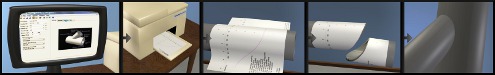
If a thick template is used, the dimension around the pipe is scaled to accurately compensate for the increased radius of the exterior of the template. The thickness specified is the added radius. This is not necessarily the measured thickness of the template. When a template is bent, the exterior of the template, where the lines are drawn, can expand so a trial and error method should be used to determine the appropriate thickness value to enter here. For a uniform density template, start with a thickness setting equal to the measured thickness of your physical template. A properly specified template will wrap around a pipe and have its angular scale meet at +/- 180 deg. When using paper templates for large pipes, a setting of 0 will be good enough for most cases.
Ordinate Lines:
Digital Pipe Fitter can generate ordinate lines on the templates as well as creating report files which include measurements for hand measured layout.
The From setting selects the location of the line from which the ordinate lines originate. The report will show the measurements from this line to the cutline. If the setting selected is inappropriate for the type of cutline generated, something reasonable will be generated. To generate the report after enabling ordinate lines, use the menu item Print/Report and select a component.
The options include:
none: No ordinate lines will be drawn.
tip of each line: Each cutline will have its own measurement line at the cutline's tip.
base of each line: Each cutline will have its own measurement line at the cutline's base.
tip of first end cut: One measurement line will be generated at the furthest point on the template so that the user can measure from the end of the pipe.
base of first end cut: One measurement line will be generated at the base of the deepest end cut so that the base ring is uncut.
first end of component: One measurement line will be generated at the first end of a cone. (The end at the top of the template as displayed on the screen.) For other component shapes the measurement line is located at '0'.
tip of second end cut: One measurement line will be generated at the furthest point in on the template (bottom of template as shown on the screen) so that the user can measure from the end of the pipe section.
base of second end cut: One measurement line will be generated at the base of the deepest end cut on the second end of the pipe section, so that the base ring is uncut.
second end of component: One measurement line will be generated at the second end of a cone. (The end at the bottom of the template as displayed on the screen.) For other component shapes the measurement line is located at '0'.
axial intersect (zero): One measurement line will be generated at the axial intersect point where the two components meet. Usually at zero on the axial axis.
surface intersect: Hole cutlines and plug cutlines are measured from their interior intersection point. This point is the '+' mark at the center of the hole where the other component intersects the exterior surface of this component.)
The Spacing setting consists of a number and a units drop-down window. Possible units are:
in: An ordinate line is drawn which repeats every specified number of inches.
mm: An ordinate line is drawn which repeats every specified number of millimeters.
points: Ordinate lines are drawn so that the cutline is equally divided by the specified number of lines.
deg: An ordinate line is drawn which repeats every specified number of degrees around the component cut.
To enable Ordinate Lines, The From setting must be something other than 'none', the Spacing setting must be something other than '0' and under Print Options, the Ordinates line style must be something other than 'NONE'.
A setting of From "base of each line" and a Spacing of 45 deg. will create templates that look more like an industry standard template created by hand. The ordinate lines make it easier to see which side of the line is the waste side.
Line colors and styles:
Specify the color and style of the various types of lines in the template and print preview window. The color value is a standard hexadecimal RGB value. It is not important to know how to generate that number, just click on the ‘pick' button to select a new color graphically.
Print full diameter templates:
When not selected, Digital Pipe Fitter will optimize the templates to use the least amount of paper possible. Checking this option will add enough paper to the template so that the template will wrap all the way around the pipe. This makes it easier to align the template on the pipe.
Print BW:
Selecting this option will print all lines on the template in black. The print preview will still be in the colors specified above.
Ignore page size
Selecting this option causes the print preview to not be fitted to the printer page size currently selected. This option can be useful if working with very large templates that will be exported to .DXF files instead of printing. When selected and viewing a template preview, the lower right hand corner of the status bar will read "No Page Size". Regardless of this setting, when printing templates the current printer settings will be used to split the template into multiple pages.
Render Background:
Always looking at a black background for 3D previews can get old. So, get wild, pick your favorite color for the background.
Render Resolution:
On slower computers the 3D rendering might be slow for complex joints. So, an option is available to specify how many points to plot around the pipe for both Print Preview and 3D Preview. You may select from several options ranging from "Fastest (low resolution)" to "Best Resolution (slowest)." If "Fastest" is selected, the template displayed could have some missing detail. If so, select a higher resolution. "Normal" is a good usable setting, only use faster settings if you have a slow computer. This setting does not affect the actual printed template, which is always printed to very high resolution.
Annotate 3D:
Check this checkbox to display component names, cutlines and orientation markings on the 3D preview. This setting has an alternate control in the button bar for easy access. This setting can also be toggled by pressing the Annotate button in the button bar or pressing ctrl-a.
Write File
Clicking "Write File" will save the current settings to a file. The default file extension for this file is .pcs .
Read File
Clicking "Read File" will load a .pcs settings file. After loading a file, if you want these new settings to be permanent, click 'Save as Default'.
Save as Default
Clicking "Save as Default" will save the current settings to be loaded the next time Digital Pipe Fitter is run. 'Restore Original' restores the factory settings.
Editing a setting and clicking the "Accept" button will change the current settings. When Digital Pipe Fitter is exited and reopened, these settings will resort back to their default state. To permanently save the settings for future work sessions, click the "Save as Default" button.
Restore Original
The "Restore Original" button will restore all settings to their factory defaults. To save these original values to be the default values for future work sessions, click the "Save as Default" button.
Cancel
"Cancel" exits the Settings dialog box without making any changes to the settings.
Accept
"Accept" saves the current settings for this work session and exists the Settings dialog box.