Printing Templates
Once you have specified the proper parameters and joint construction, you can print the templates. Either the print button or the ‘Print' menu item can be used to print. The print button only prints the currently viewed previewed template. Starting in version 1.62, it is possible to print to AutoCad® DXF files. On the 'Print' main menu, select 'Export DXF' and then select the component to export. Next you will be prompted for the name of the file to create. Starting in version 1.7, it is possible to print reports which show the template on one page along with ordinal measurements to be used to hand layout a cutline. On the 'Print' main menu, select 'Report' and then select the component to export. The colors of the lines used to print the templates and shown in the print preview windows can be specified under the menu item "Options - Settings". 
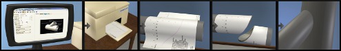
If the template is larger than the paper specified in the "File -Printer Setup" and "File - Page Setup" dialog boxes, multiple pages will be printed. There are alignment marks in the corners of the pages to aid in taping the pages together to make a large template. You do not have to print all the pages of the template. The print dialog box has the option to only print the range of pages you want. Click the mouse on the thumbnail of the template in the print dialog box to select the pages to print. Hold down a Shift key on the keyboard and click to select regions to print or not print. Prior to version 1.7 a range of pages to print can be specified by number in the print dialog box. Digital Pipe Fitter will print to any printer that Windows can print to, including large format inkjet plotters. Printout ExplainedThe lines on the template and Print Preview are rendered with the colors specified in the settings window. You may download this sample printout of a template to follow along. Exterior Cut Line: The exterior cut line is always drawn. It shows where to cut. If it appears without an interior cut line, then the intent is to cut along this line with the cutting tool perpendicular to the surface of the pipe. Interior Cut Line: The interior cut line is only printed for bevel cut construction types. This line indicates where to cut on the interior of the pipe. You will need to visually project the line toward the centerline of the pipe and estimate where it intersects the interior surface of the pipe. Axis: The axis is marked in the current units of the joint being printed. The angle measure on the horizontal axis can help in registration of the template on the pipe. The axial measurement assumes that 0 is the point of intersection of the centerlines of the two components (or pipes). If the shapes of the two components are not pipes, this definition may change. For example if intersecting a flat plate, the 0 point is where the center of the pipe intersects the top surface of the plate. After you print a template, check the axis measurements with a ruler to make sure your printer is printing to the proper scale. On a cone shaped component, the vertical axis measurements show the distance along the axis of the component. It is not a measurement along the outside surface of the cone. The measurements do not represent linear distance along the template. This scale will be expanded depending on the flare of the cone. Guide Lines: Additional guidelines are show to aid in the alignment and interpretation of the template. 180deg and 90deg alignment lines: 180deg alignment lines are shown where the template should meet on the far side of the pipe. If these two lines do not coincide when wrapped around the pipe, either the pipe diameter specified was not correct or the template thickness setting on the Settings window needs to be adjusted. Or perhaps your printer is not printing accurately. 90deg alignment lines are also shown to help align the template. Also, a scale on the horizontal axis shows angles of rotation around the pipe so the template can be oriented at any angle of rotation from an existing feature on the pipe. Alignment Triangles: Triangles are shown on each cut line to help align the two components. These triangles (or diamonds) are always pointed toward the waste side of the cut. Think of it in terms of, "cut along this line so that the triangle points toward the waste side of the cut. The triangle is located at the same point on both templates to aid alignment after cutting. You might want to make a mark on the pipe at that point before removing the template to aid in assembling the physical joint. Starting in version 1.7, the triangles contain a character to indicate the type of cutline they are associated with.
Ordinal Lines: If enabled in version 1.7 and above, the "Options - Settings" window, ordinal lines have several purposes. First, when shown in a printed report they specify the location and number of points shown for hand layout. Also, they help orient the user to know which side of the cutline is the waste side. The base band is always on the pipe side of an end cut. Page markings: Blue page markings are also provided on the Print Preview to help you decide what pages to print out and to know how many pages will be printed. These marks are not printed on the actual printout. Alignment marks are added to the printout to aid in aligning multiple pages together. Each printed page also has a small picture of where this sheet fits into the whole collection of pages. Parameter Settings: The parameters for a particular joint are printed on the first page including the joint name and the type of joint.
|

Note that printing is only available if you have a properly licensed copy of Digital Pipe Fitter installed on your computer. To help evaluate this software and test compatibility with various printers, sample printouts may be made of a