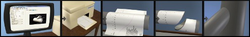
The Cone Bevel Joint is the intersection of the end of one cone shaped component, with a flat plate.
This joint is similar to the standard bevel joint except it works with a conical shape instead of only cylinders.
Where the pipe in a bevel joint has assumed infinite length and a single constant diameter, a cone component has a fixed length and usually different diameters on each end. Cone components also need to be positioned along their axis, so a parameter Org (for Origin) is also specified. Org is the distance from the first end opening of the cone to the intersection point of the joint. So, for example if the cone has a length of 10 inches and an Org of 5 inches, then the axis of the cone component will intersect the top surface of the plate half way along the cone's length.
Two templates are created. One for the end of the cone component and another for the hole in the plate component.
The templates can contain cutlines that assume the cone component extents past it's specified length. This is done for several practical reasonons and for consistancy. As a result, unexpected cutlines my be generated that the user might choose to ignore. Be sure to view the joint in the 3D preview to confirm that it is what you expect.
Parameter Constraints:
Joint Name: name of this joint which is unique to this project or currently opened joints
Cone OD: outside diameter of first end of the cone component (must be a positive number)
Cone OD2: outside diameter of second end of the cone component (must be a positive number)
Cone Len: length of the cone component (must be a positive number)
Cone Org: the distance from the first end (OD) of the header component where the intersection with the top surface of the plate will be (This parameter positions the cone component along its axis relative to the plate component.)
Cone Wall: must be a positive number, less than half of the smallest diameter (Cone OD or Cone OD2)
Plate Wall: must be a positive number
Bevel Angle: between 0 deg. and 180 deg. (90 deg. is a perpendicular joint.)
Joint Construction Notes:
For an "On Far Surface" construction, the plate template is sized to fit snug around the cut end of the cone component. There will never be a gap between the cone component and plate component as long as the cone component are long enough to complete the joint and thier orientation allows the joint to exist. The best example of this optimization is when both components bevel type is set to 'Perpendicular Cut'.
Whenever possible, even if no cutline is generated, a 3D preview will be available to help orient the two components. The 3D preview simplifies the task of entering parameters into this complexity joint type since the orientation of the two components can usually be seen. If the cone component is not visible in the 3D preview, then likely it is completely below the plate intersect surface. In order to see where the cone component is, try temporarily changing the joint constrution, cone ends setting to "All the Way Through". Then the cone should become visible.