Imagine a small pipe joined perpendicular to a larger pipe through its middle. There are several very different joints that can result. First the end of the small pipe could rest on the outside surface of the larger pipe. Or perhaps the smaller pipe is inserted into a hole in the side of the larger pipe and the end of the small pipe is cut so that it does not obstruct flow of liquids through the main pipe. In the second case, the end of the small pipe is cut to match the interior surface of the large pipe. Another case is when the small pipe enters all the way into the interior of the large pipe and has no particular ending point. Or, what if the small pipe should enter through the hole in the side of the large pipe and rest on the opposite inside surface of the large pipe. Or, the small pipe could go on through a hole in the opposite side of the large pipe and get cut flush with the far outside diameter of the large pipe. Or, the small pipe could go all the way through the large pipe, through two holes on opposite sides of the large pipe, and continue on without an end cut.
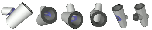
The above paragraph describes six completely different interactions of two pipes. Each interaction results in a very different template with different cut lines. You must specify which construction you want to create in the Joint Construction section of the parameters area of the joint window. Some joint types by definition will only result in one type of construction, in those cases no input field will appear.
If a joint type supports more than one of these construction options, the setting can be found in the Joint Construction input area at the bottom of the parameter input window. See the branch joint documentation for an example of joint construction options.
Also, in the Joint Construction input area is a set of fields to specify the type of bevel cut you plan to make. Usually three different methods of creating a bevel are supported for each unique component in the joint.
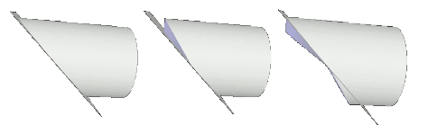
Bevel Cut: Two cut lines are generated, one for the exterior and one of the interior of the component. The interior cut line is drawn on the template that will be wrapped around the physical component, so the user needs to visualize the line projected toward the center of the pipe and estimate where it intersects with the interior of the pipe. Then an angled cut must be made at the right angle to run along both the exterior cut line and the imagined interior one. This can be a difficult task.
Perpendicular Cut: It might be sufficient for your application and most likely easier to do straight cuts perpendicular to the surface of the pipe. But for the two pipes to fit together correctly, sometimes you will need to cut on the interior intersect line and sometimes on the exterior intersect line of a bevel cut template. The perpendicular cut option makes that decision for you. It creates a singe cut line which, when cut perpendicular to the surface, will result in a properly made joint that needs no material removal for a perfect fit. This type of joint will always remove more material than a ‘Bevel Cut' joint so there will be exposed bevels on the resulting joint. This methodology may be fine if you are welding the pipes together but might not be appropriate for an adhesive based joint.
See cut optimization for how Digital Pipe Fitter avoids gaps that would normally occur in some Perpendicular Cut joints.
Hand Beveled: In a Hand Beveled joint, the opposite decision is made by the software as was made in the perpendicular cut. A single cut line is generated which removes the least possible amount of material when cut perpendicularly to the surface. Cutting along this line perpendicularly results in an area of interference between the components that needs to be hand beveled to result in a cut identical to the ideal bevel cut option. This interference can be viewed in the 3D rendered view.
The above descriptions may not exactly describe the cut lines generated for a hole in the side of a pipe. An attempt is made to result in a reasonable joint in cases where the standard description above would result in an unusable joint. Luckily, the 3D rendered view will show exactly what the resulting cut creates, so there is no confusion.